11. Managing Alarms
Alarms are highly important aspect of Condition Monitoring, Condition Based Lubrication, and virtually any kind of measurement that needs to be compared with previous condition or any reference value. Alarms make managing database, decisions, and tasks much easier, and in some cases, they determine the field work. UAS3 offers excellent alarm system, covering all your needs, and still easy to work with. Alarms thresholds should be set based on data, understanding assets behavior and condition. This is a topic of our training, so feel free to contact us.
As an introduction, let us start with basic rules, instructions:
- If working with SDT270 or LUBExpert database, Alarms can only be attached to Static measurement, as there are both Dynamic and Static
- If working with SDT340 database, Alarms can be attached Measurement, as there is no difference between Dynamic and Static, it is unique measurement point
Types of Alarms:
- Absolute
- Absolute Alarm monitors measurement value and compares it with defined alarm thresholds, triggers if measured value exceeds thresholds
- Safe
- Safe Alarm monitors measurement value and checking if it is within defined range,where lower and upper threshold is defined
- Relative
- Relative alarm monitors relationship of the measured value with first measurement, previous measurement, or referent measurement, whether increasing or decreasing
Alarms monitor indicators:
- RMS
- maxRMS
- Peak
- Crest Factor
Alarms differ by way they are created and managed
- Alarms in Template
- This is where you create your alarms to use them frequently, on many assets.
- Consider it as “alarm bank”. You create alarm, save it, and apply it when and where you need it
- Node Alarms
- Locally created alarm (in the measurement itself). It is not saved in the “alarm bank”, it is considered custom. If needed, it can be transformed to template alarm
11.1. Creating Alarm in Template
In Top toolbar, left click on Utilities and select Alarm Functions, as below:

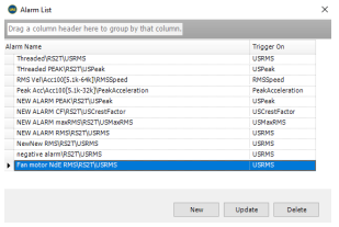
Right click Alarm Functions and Alarm List window will pop up, for alarm management:
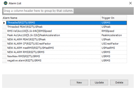
Here, you see Alarms that you already created. You can delete them, update them (change the settings), or create new. First, let us create New Alarm. Left click on New Alarm (at the bottom of Alarm List window)
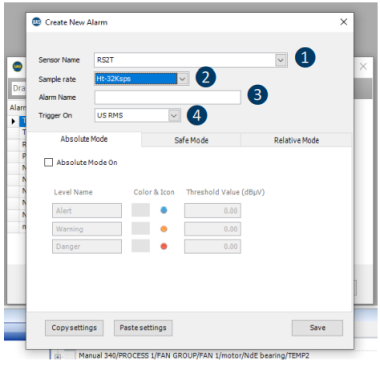
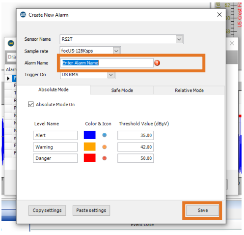
❶ Choose sensor that alarm will be applied to - Each defined alarm is defined for one sensor
❷ Choose sampling rate (in case of SDT340) - Different sampling rates define measurements as different, even if sensor type is the same
❸ Choose Alarm Name - Choose intuitive name. Soon you might have lots of alarms here, and it is important to be able to differentiate them easily
❹ Choose indicator to be monitored - Each alarm monitors one indicator. To monitor other indicator as well, create additional alarm
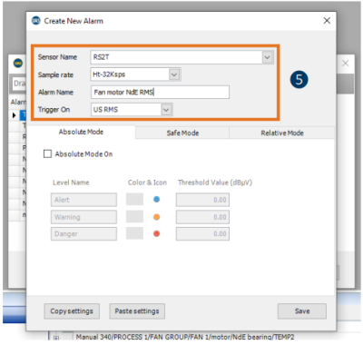
❺ Here we decided to create and alarm for RS2T sensor, for the measurement of 32.000 samples per second, we gave it a name “Fan motor NdE RMS” (as we need it for that
position), and this alarm will monitor RMS value.
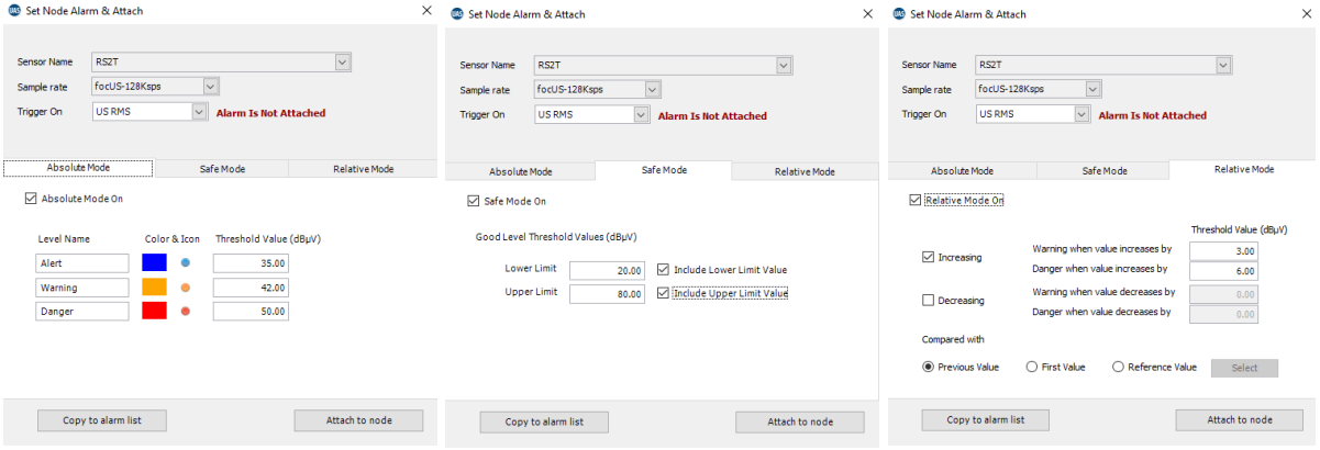
Now we can define Alarm’s thresholds, starting with Absolute Mode, as below:
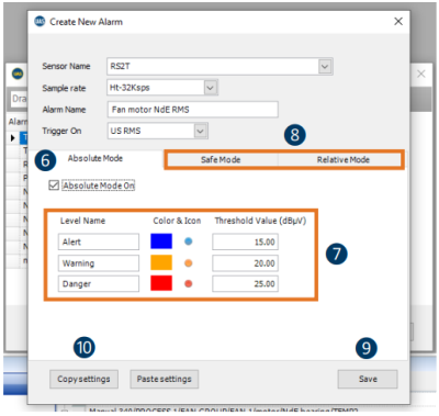
❻ Left click on Absolute Mode On checkbox to activate this alarm Mode.
❼ Enter alarm threshold values for Alert, Warning and Danger. Warning value must be higher than Alert value and Danger value higher than Warning value.
❽ If we plan to ad Safe Mode and Relative Mode, we will click on their tabs, and not save the alarm yet.
❾ If we plan to add only Absolute Mode, we will click on Save.
❿ If we plan to add more alarms with similar settings, we can use Copy settings/Paste settings function.
Let us add Safe Mode as well:
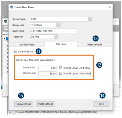
⓫Left click on Safe Mode On checkbox to activate this alarm mode.
⓬Enter alarm threshold values for Lower and Upper Limit and confirm if threshold should be included.
⓭If we plan to add Relative Mode as well, we will click on its tab, and not save the alarm yet.
⓮If we plan to add only Absolute and Safe Mode, we will click on Save.
⓯If we plan to add more alarms with similar settings, we can use Copy settings/Paste settings function.
Add Relative Mode also:
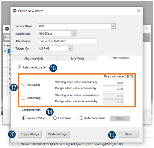
⓰Left click on Relative Mode On checkbox to activate this alarm mode.
⓱Enter alarm threshold values for Lower and Upper Limit and confirm if threshold should be included.
⓲Define reference for comparison.
⓳If we finished setting, we will press Save.
⓴If we plan to add more alarms with similar settings, we can use Copy settings/Paste settings function.
Our Alarm is defined:
Same way, we can define alarms based on other indicators and on other sensors.
Four alarms can be attached to one single measurement, one per each indicator, each alarm in three different modes, providing excellent coverage.
11.2. Assigning Alarm from Template to single measurement
Alarm from Template can be assigned to single measurement in several ways, but directly by selecting a measurement in Tree Structure is certainly most simple and straightforward.
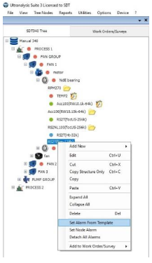
To do that, right click on measurement (in case you are working with SDT270 or LUBExpert, choose Static measurement) and select Set Alarm from Template:
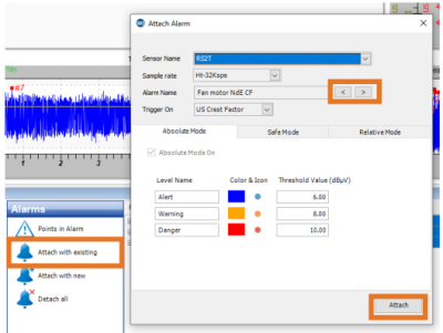
And Attach Alarm window will pop up:
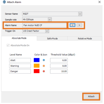
UAS3 automatically filters available Alarms for the sensor in the measurement you selected, making search much faster and easier. All you need to do now is browse through alarm using left and right arrows in Alarm Name field and look for the alarm you created for this measurement point. Once you find right alarm, simply click Attach. Alarm is attached and you can proceed attaching other alarms if needed.
11.3. Assigning Alarm from Template to multiple measurements
Alarm from Template can be assigned to multiple measurements from the Bottom Pane.
To do that, select the node in your Tree Structure that contains all that you want to find and add alarm to. Left click on that node and look at the Bottom Pane.
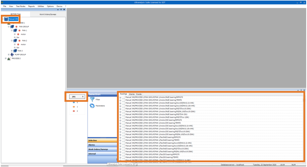
I selected Database Root, 1st level, and all measurement it contains are now displayed in Bottom Pane. All 291 of them, as you can see right above the traffic lights.
Next thing you need to do is to filter measurements you are interested in. Let us say that you want all NdE bearings on all electrical motors on fans, measured with RS2T sensor at 32.000 samples per second, in Process 1.
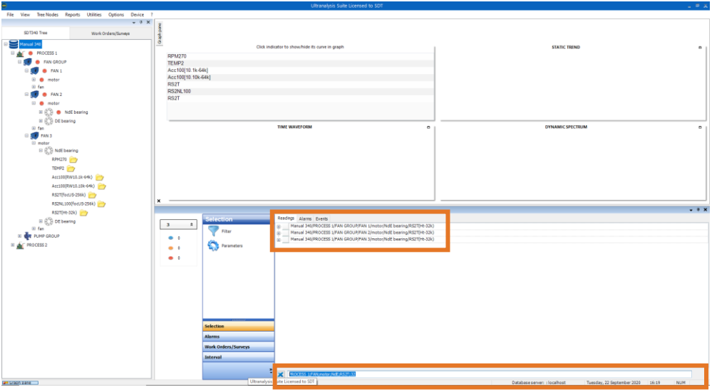
Left click on Selection in Bottom Pane toolbox and select Filter. Search bar on the bottom of Bottom Pane will appear and you should enter search criteria. NOTE! If you work with SDT270 or LUBExpert, add additional criteria: ST (to filter out Static measurements only).
In this case: PROCESS 1; FAN; motor; NdE; RS2T; 32
We filtered out all measurement that comply with criteria, and here they are, three of them:
Now, you need to select all three measurements by using "shift" or "ctrl". Then left click Alarms tab in Bottom Pane toolbox.
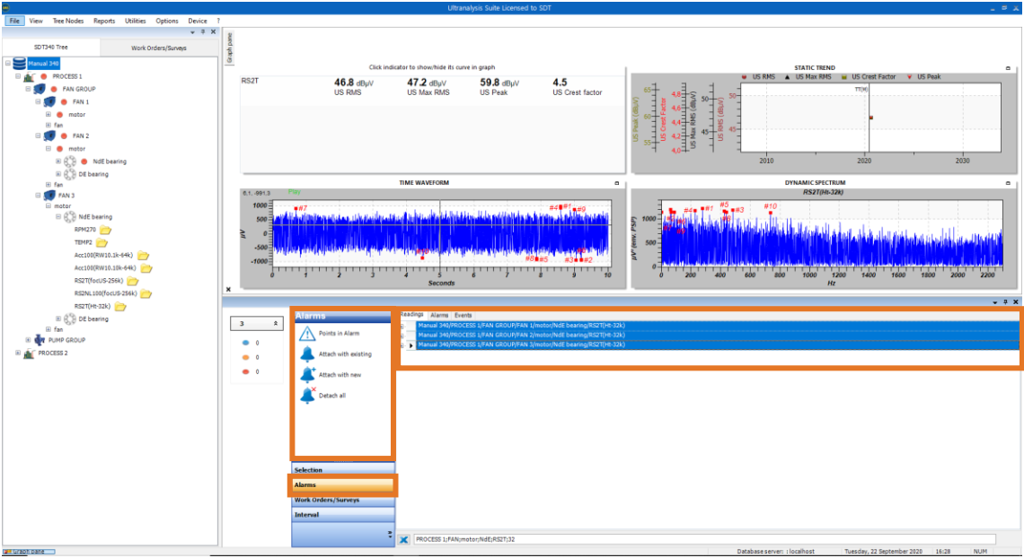
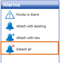
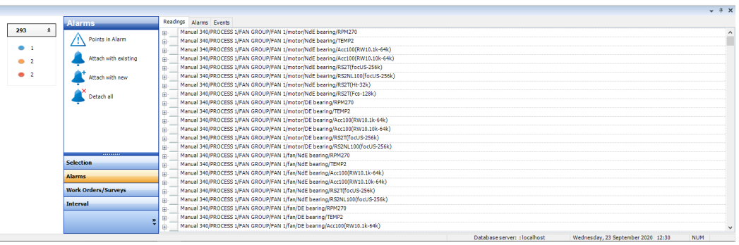
Alarm field appears in Bottom Pane toolbox. Let us examine offered commands:
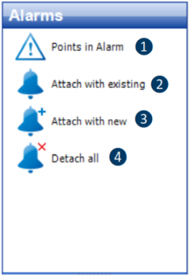
❶ Show all points in alarm
❷ Attach existing alarm to selected measurements
❸ Attach with new alarm (direct link to creating a new alarm)
❹ Detach all existing alarms from selected, measurements
Since you already created Alarm, you should choose Attach with existing (left click on it), and Alarm windows will appear.
Select alarm you want to attach (browse through the alarm list with arrows in Alarm Name field) and click on Attach.
Alarm is now attached to all three measurements.
Repeat it if you want to attach more alarms.
11.4. Setting Node alarm to measurement point
As mentioned before, Node Alarm is locally created alarm (in the measurement itself). It is not saved in the “alarm bank” and it is considered custom. If needed, it can be transformed to template alarm. Let us see how you will create/assign this alarm: Right click on measurement you want assign Node Alarm to and choose Set Node Alarm, as below:

Set Node Alarm window will pop up
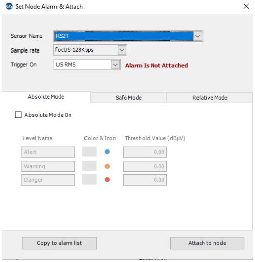
Process of defining alarm parameters is the same as it is in Alarm in Template:
- Sensor field and Sample Rate fields are not editable – it is the same sensor and same Sample Rate as in measurement point you selected.
- You need to choose indicator you want your Alarm to monitor: RMS, maxRMS, Peak, and Crest Factor
- Activate and assign thresholds to Absolute, Safe and Relative Mode, or just one or two of them
All is set, and now click on Attach to node and you Node Alarm monitoring RMS is attached and active. Now you can add another alarm, monitoring another indicator.
Node alarm is assigned to selected node only and does not exist in Templates (“Alarm Bank”).
When you try to assign next Node Alarm to same measurement (after you assigned one as in previous example), you will be warned about alarm that is already assigned, as below:

Alarm on RMS indictor is already attached. Change indicator and see if another indicator can be attached.

If, at any moment, you decide to use this Node Alarm for other measurement positions as well, click on Copy to alarm list, and you can add it to template:

Click on Copy to alarm list andCreate New Alarm window will pop up. Now, you need to assign a name to this alarm, and you will have it in Template Alarm as well.
11.5. Detaching Alarms
Alarm can be detached from a single measurement or multiple measurement.
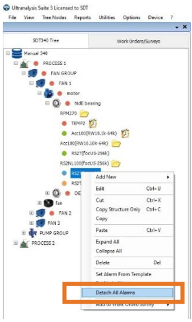
Same as attaching alarm in Tree Structure, right click on measurement and select Detach All Alarms.
If there is more than one alarm attached to measurement point, and single or more alarms should be
removed, not all:
Left click on measurement in Tree Structure.

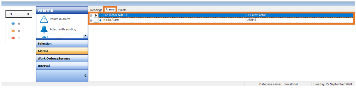
In Bottom Pane select Alarms tab and you will have all attached alarms displayed
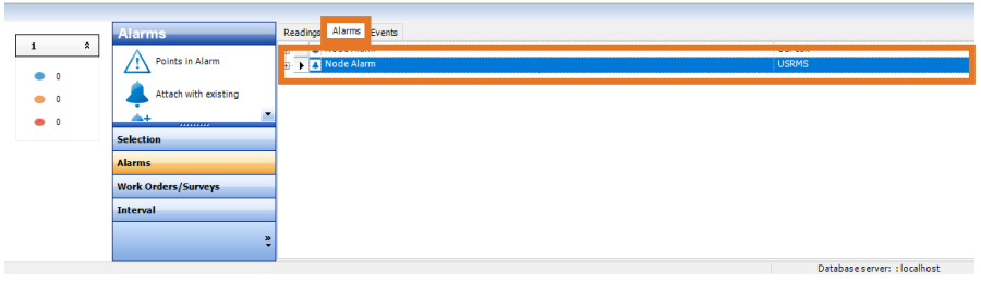
Right click on each of the alarms enables you do detach single alarm, while leaving all other alarms attached.
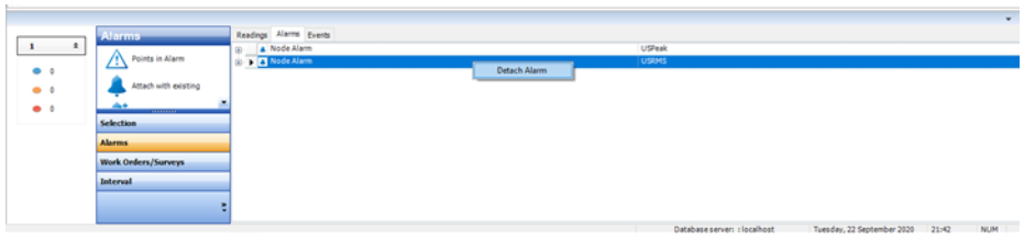
Alarm can also be detached in Bottom Pane, where you can also detach alarm from multiple measurement points. Select measurement in the same way as you selected them in attaching process and click on Alarms in Bottom Pane toolbox.
Simply click on Detach all, and alarms will be removed from all selected measurements.
11.6. Overview of attached alarms
To overview alarms attached to measurement point, left click on measurement point.

In Bottom Pane select Alarms tab and you will have all attached alarms displayed. Small bell icon indicates Node Alarm, while alarm without bell icon is Alarm from Template.
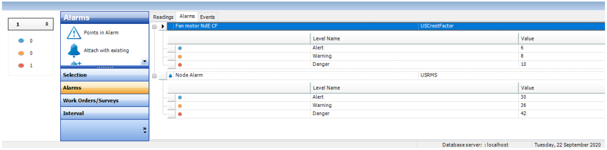
Left click on small “+” in a box next to alarm name and details about assigned alarm will be displayed.
11.7. Alarm status displayed
Once alarm is triggered by measurement outside of alarm threshold, it will be displayed in several ways and several places.
11.7.1. Alarm status displayed in Tree Structure through Traffic lights
- No traffic light – Alarm not assigned, or assigned but still no measurement recorded
- Green – Alarm assigned, but not triggered
- Blue – Alert
- Orange – Warning
- Red – Danger
Alarms are triggered at measurement level, but they are transferred through hierarchy to each Parent Node. Each Parent Node will be assigned with highest triggered alarm among all measurement points in all child nodes.
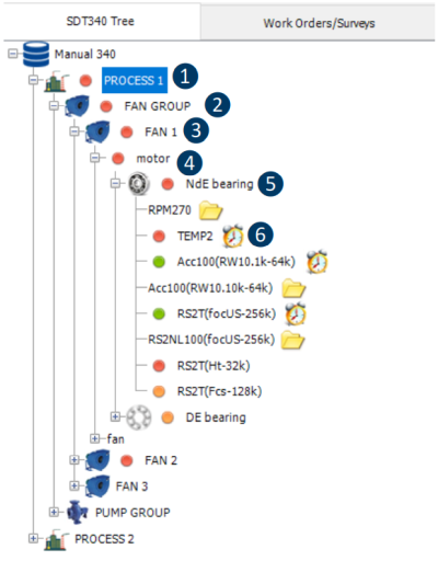
❶ PROCESS 1 - Danger status
(Child Node FAN Group is in Danger status)
❷ FAN GROUP - Danger status
(Child Nodes FAN1 & Fan2 in Danger status)
❸ FAN 1 - Danger status
(motor is in Danger status)
❹ Motor - Danger status
(NdE bearing is in Danger status)
❺ NdE bearing - Danger status
(At least one of the measurements is in Danger status)
❻ TEMP2 & RS2T 34k triggered Danger status
11.7.2. Alarm status displayed in measurement Matrix
Once alarm is triggered by measurement outside of alarm threshold range, it will also be displayed in measurement Matrix. Indicator triggering alarm will be displayed in color corresponding with triggered alarm level. In case as below, Matrix is showing four most recent readings and showing us alarm status for each indicator:
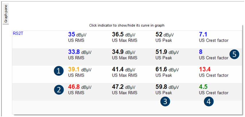
❶ Alarm assigned and in Warning status
❷ Alarm assigned and in Danger status
❸ Alarm NOT assigned
❹ Alarm assigned and NOT triggered
❺ Alarm assigned and in Alert status
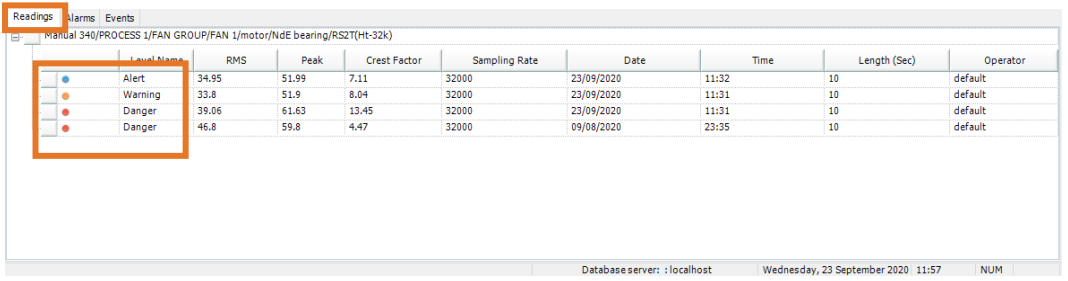
11.7.3. Alarm status displayed in Bottom Pane
When measurement is selected in Tree Structure, Bottom Pane displays readings details in Readings tab. Traffic lights indications represent alarm status. No matter how many indicators have assigned alarm or how many of them are triggered to any status, highest alarm level be displayed in front of the reading data, as shown below:
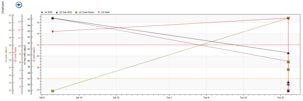
11.7.4. Alarm status displayed in Static Trend Graph
Alarm threshold levels are shown in Static Trend Graph as lines in color corresponding with alarm level (Red, Orange and Blue), as below:
11.8. Shortcut to points in alarm
Bottom Pane toolbox contains an interactive Traffic Lights Tool that displays total number of measurements in alarm for each alarm level.
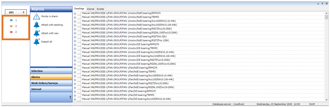
Left click on alarm level and your Tree Structure will open the measurement in alarm, as below:
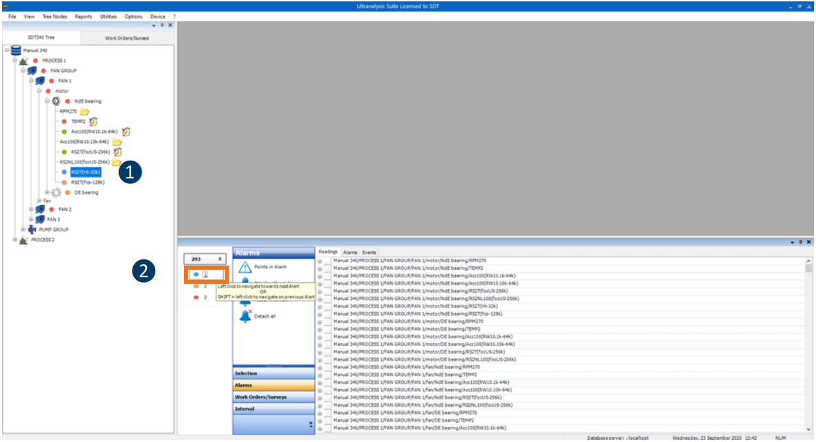
❶ Point in alarm displayed
❷ Left click on alarm indicator
If there is more than one point in alarm at certain alarm level, every time you left click on alarm indicator, next measurement in alarm will be displayed.
11.9. Overview and action on points in alarm
In Bottom Pane toolbox, left click on Alarms and select Points in Alarm
Points in Alarm window will pop up:
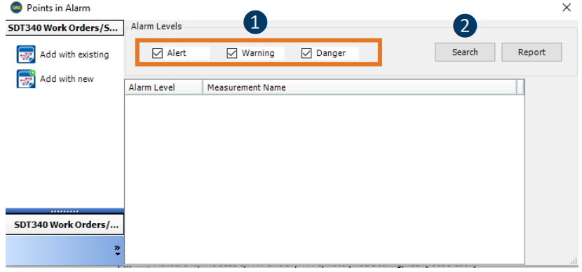
❶ Select alarm level to search for points in alarm
❷ Click on Search
All measurement points in selected alarm(s) will be displayed. Select measurement point(s).
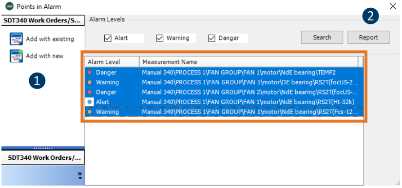
❶ Add selected measurement point in alarm to existing or new survey
❷ Generate Report containing all selected Points in Alarm