10. Creating and Editing Tree Structure
As mentioned before, building a tree structure is like laying a foundation: If done correctly, all further actions will be much easier. Decide about Tree Structure logic and take following in consideration:
What assets are connected by process? What assets are connected by location? What assets belong to same type, or same manufacturer? What assets are redundancy?
There are many criteria, but target is always the same: Your data needs to be organized in a way that reflects reality. Tree structure needs to offer easy overview, filtering, and conclusion to one who uses it, as well as clean and straightforward work order/survey for one collecting data/inspecting. Take good care about names: lower case, upper case, space … makes a difference.
Nomenclature needs to be decided, and whatever the decision is, all involved need to follow it. Otherwise, database will be useless, source of many frustrations and it will consume a lot of your time and time of those who need to collect data. Apart of proper creation of Tree Structure, each measurement point needs strictly defined measurement settings.
10.1. Adding Nodes
Note
All functions explained here, done directly in the Tree Structure with right and left click, can also be executed from Top toolbar, selecting Tree Nodes, as shown below:

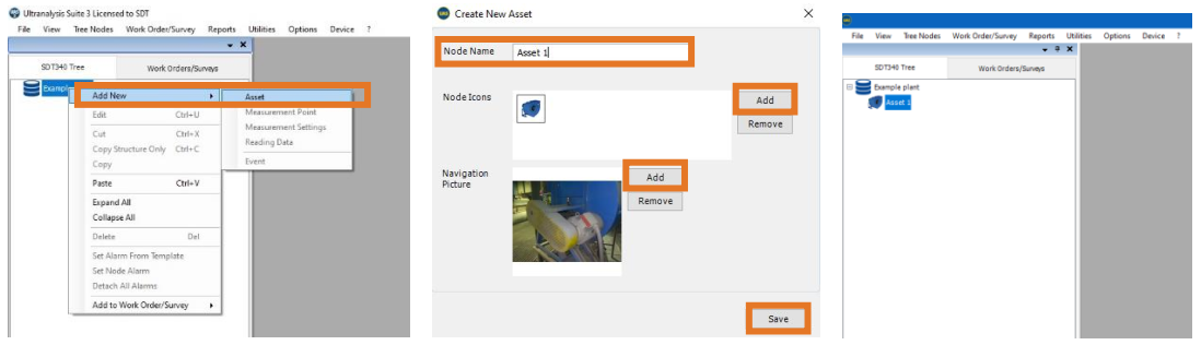
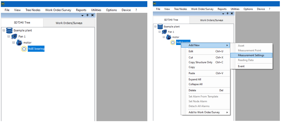
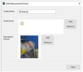
Right click on the Database Name or on an existing Node. On the drop-down menu select Add New and then select Asset. Add Node Name (up to 30 characters). You can add Node Icon and Navigation Picture to your asset, as shown below:
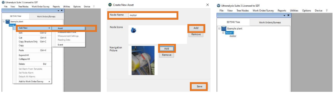
Now there is a first level in your Tree Structure. At this point, we can add Asset, Measurement Point or Measurement Settings to already added Asset 1. Let us add another Asset, in this case an electrical motor. Right click on Asset 1, Add New, and select Asset. Same as in previous step, you can add Node Icon and Navigation Picture.
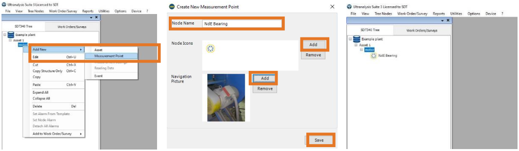
At this stage, we added Asset, then we added an electrical motor that is part of that Asset. Now, let us add Measurement Point, a bearing. Right click on motor, Add New, and select Measurement Point.
As you can see, we did not use all available levels, as we did not need them. At this stage, we arrived at Measurement Point. Next (and only) thing we can do, and need to do, on Measurement Point is Measurement Settings. But first, let us Edit a Node.
10.2. Editing Nodes
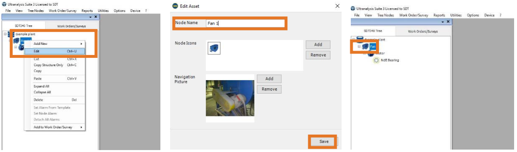
In case you need to edit any of data you added to node, right click on Node you want to edit and select Edit. As we previously added Asset 1, we will change it now in Fan 1.
10.3. Adding a Measurement Settings
Following Tree Structure architecture and naming importance, Measurement Settings are critically important and often partially determine the quality and usefulness of collected data. Measurement Settings contain information about type of the sensor used, interval of data collection, acquisition time. In some cases, also filter frequency, sampling rate, emissivity. In case of Lubrication, Measurement Settings contain even more information. Let us see case by case. Note that Measurement Settings can be added only to Measurement Point and cannot exist in same parent node at the same level as Asset or Measurement Point.
10.3.1. Measurement Settings for SDT340
In case of previously added Motor NdE bearing in Fan 1, we would like to define several different measurements that need to be collected regularly.
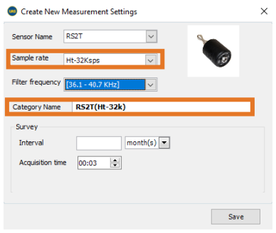
Create Measurement Settings window that pops up will look like this:

First, choose a sensor. In Sensor Name window, press arrow for drop down menu. Only sensors you selected in System Settings will be displayed. Select needed sensor and continue with settings. In this case, we will choose Ultrasound sensor.

Next, we need to select Sample Rate. Left click on Sample Rate window arrow for drop down menu and select needed Sample Rate. You can choose between 32.000, 128.000, and 256.000 samples per second for contact sensors while Sampling rate for airborne sensors is fixed at 32.000 samples per second.

Filter Frequency Setting for Ultrasound sensors is fixed at displayed frequency band. Category Name is non-editable field.
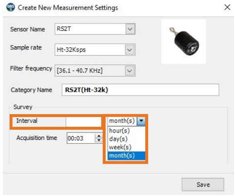
Interval defines how often data needs to be collected, and it is a mandatory field. It will help you organize your surveys/work orders better by being able what tasks need to be done in coming period. Interval definition is product of your understanding of the asset and needs to come from your Criticality Analysis, Failure Mode & Effect Analysis, DIPF Curve for certain asset and certain defects, sometimes even from Failure Rate and Root Cause Analysis. Interval too long can result in anomaly development not being detected at early stage, and interval too short will have a detrimental effect of your work optimization, spending your resources unnecessarily (in this case, manpower).Interval in UAS3 Measurement Settings can be defined in Hours, Days, Weeks, and Months. Left click on time unit window, select unit, and enter the value in Interval window.
Finally, you need to define Acquisition Time. Acquisition time is duration of a single measurement, recorded reading. Acquisition Time needs to be decided based on asset operation conditions.
Primary factor affecting acquisition time is rotating speed (in case of rotating assets) or process itself.
In case of bearings, we would like to record at least 3-5 revolutions, preferably 5-7 revolutions. As not all Assets inspected by Ultrasound are rotating, consider process itself. Take hydraulic valve as example and consider that you need to wait for its operation as well as record the operation itself.
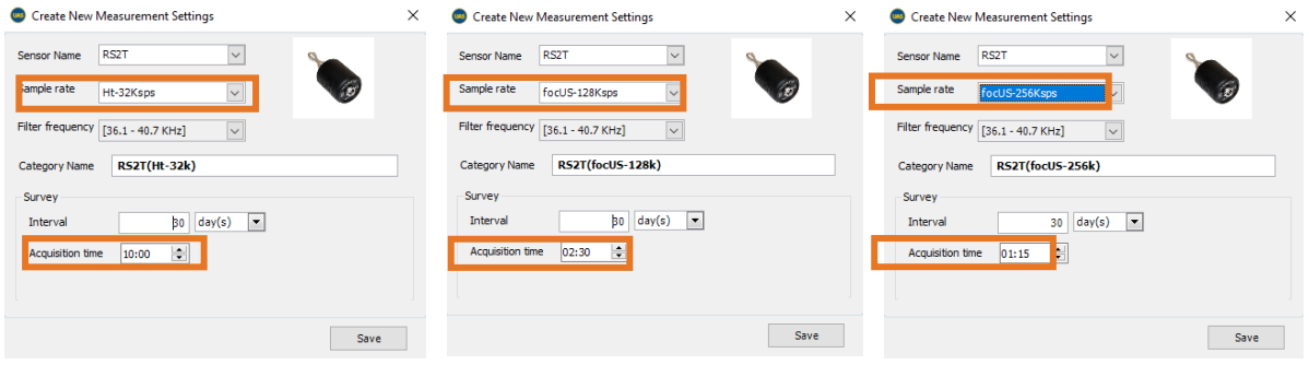
Not that in SDT340 maximum Acquisition Time depends on Sample Rate.
- 32.000 samples per second - maximum Acquisition Time is 600 seconds (10 minutes)
- 128.000 samples per second - maximum Acquisition Time is 150 seconds (2 minutes and 30s)
- 256.000 samples per second - maximum Acquisition Time is 75 seconds (1 minute and 15s)
In case we choose Vibration sensor, Accelerometer, some details will be different. Choose the sensor, in this case Acc100.

Next, we need to select Sample Rate. Left click on Sample Rate window arrow for drop down menu and select needed Sample Rate. You can choose between 32.000 and 64.000 samples per second.

Filter Frequency Setting for Vibration sensor can be adjusted int three ranges:
- 5 – 1000 Hz
- 10 – 1000 Hz
- 10 – 10000 Hz
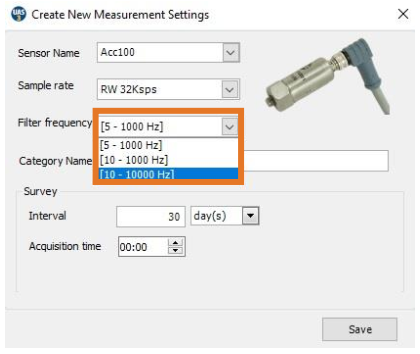
Category Name will reflect your Frequency range settings, therefore considering different Frequency range practically as a different sensor, displaying it separately in Measurement Point.
Interval defines how often data needs to be collected, and it is a mandatory field. It will help you organize your surveys/work orders better by being able what tasks need to be done in coming period. Interval definition is product of your understanding of the asset and needs to come from your Criticality Analysis, Failure Mode & Effect Analysis, DIPF Curve for certain asset and certain defects, sometimes even from Failure Rate and Root Cause Analysis. Interval too long can result in anomaly development not being detected at early stage, and interval too short will have a detrimental effect of your work optimization, spending your resources unnecessarily (in this case, manpower). Interval in UAS3 Measurement Settings can be defined in Hours, Days, Weeks, and Months. Left click on time unit window, select unit, and enter the value in Interval window.

Finally, you need to define Acquisition Time. Acquisition time is duration of a single measurement, recorded reading. Acquisition Time needs to be decided based on asset operation conditions.
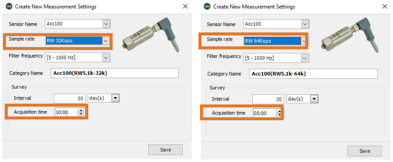
Not that in SDT340 maximum Acquisition Time depends on Sample Rate.
- 32.000 samples per second - maximum Acquisition Time is 600 seconds (10 minutes)
- 64.000 samples per second - maximum Acquisition Time is 150 seconds (2 minutes and 30s)
If Temperature Sensor is selected, Interval and Emissivity need to be defined.
Considering Interval, all mentioned before applies. Of course, Interval for all different measurements taken on one Asset should be the same, for practical reason. If they differ as outcome of analysis, shortest Interval should be the choice.
In regard to Emissivity, you can look up in publicly available material about Emissivity for each surface material or look up for procedure to measure it yourself. However, for comparison and trending purposes, leaving Emissivity at value 1 would not be a mistake, but consider that temperature value in your reading is not exact.

You can also add RPM sensor, in case of you only need to define Interval. To execute the measurement, you will need to place reflective tape, so please refer to SDT340 manual.

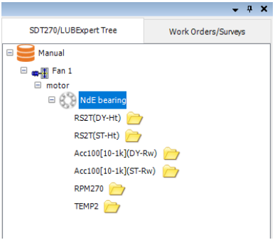
Now, when we added as many Measurement Settings in our Measurement Point as we need, it will look like this:

Small folder icon next to your sensor level means that it does not contain any data yet.
10.3.2. Measurement Settings for SDT270
When building Tree Structure for SDT270 and LUBExpert, there is a small difference; instead of Asset, Measurement Point and Measurement Settings, you will see Tree Node and Measurement Settings.
In case of previously added Motor NdE bearing in Fan 1, we would like to define several different measurements that need to be collected regularly.

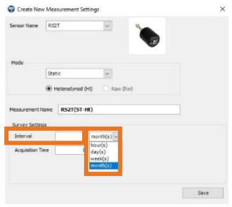
Create Measurement Settings window that pops up will look like this:
First, choose a sensor. In Sensor Name window, press arrow for drop down menu. Only sensors you selected in System Settings will be displayed. Select needed sensor and continue with settings. In this case, we will choose Ultrasound sensor.
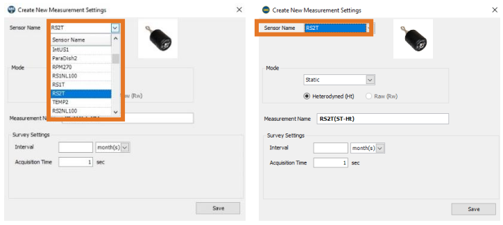
Sample Rate in SDT270 is fixed for all sensors, so you will not be setting it as a measurement parameter. However, there is additional settings that needs to be done in SDT270 and LUBExpert that is not needed in SDT340.
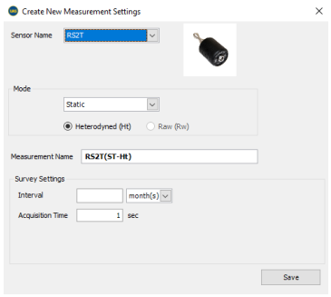
Setting Dynamic or/and Static measurement mode.
When using SDT270 with Dynamic measurement feature, you need both Dynamic and Static settings in your Measurement Point (Tree Node). In case Static point is not defined it will be auto created with first measurement (if measurement is performed in Survey Mode, through Work Order).

Measurement Name will be generated, containing Sensor name, Measurement Mode (ST or DY, Static or Dynamic) and it will contain Ht or Rw (Heterodyned for Ultrasound and Raw for Vibration). Interval defines how often data needs to be collected, and it is a mandatory field. It will help you organize your surveys/work orders better by being able what tasks need to be done in coming period. Interval definition is product of your understanding of the asset and needs to come from your Criticality Analysis, Failure Mode & Effect Analysis, DIPF Curve for certain asset and certain defects, sometimes even from Failure Rate and Root Cause Analysis. Interval too long can result in anomaly development not being detected at early stage, and interval too short will have a detrimental effect of your work optimization, spending your resources unnecessarily (in this case, manpower). Interval in UAS3 Measurement Settings can be defined in Hours, Days, Weeks, and Months. Left click on time unit window, select unit, and enter the value in Interval window.
Finally, you need to define Acquisition Time. Acquisition time is duration of a single measurement, recorded reading. Acquisition Time needs to be decided based on asset operation conditions.
Primary factor affecting acquisition time is rotating speed (in case of rotating assets) or process itself.
In case of bearings, we would like to record at least 3-5 revolutions, preferably 5-7 revolutions. As not all Assets inspected by Ultrasound are rotating, consider process itself. Take hydraulic valve as example and consider that you need to wait for its operation as well as record the operation itself.

Note that in SDT340 maximum Acquisition Time for SDT270 is 80 seconds.
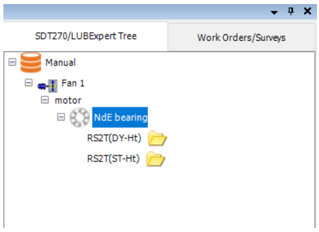
Now, if you prepared setting for Dynamic readings, add new settings with all equal parameters except Measurement Mode – choose Static. Or vice-versa.
Your settings will look like this:

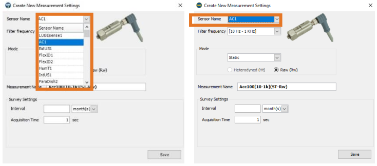
In case we choose Vibration sensor, Accelerometer, some details will be different. Choose the sensor, in this case Acc 1.
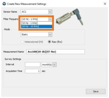
Sample Rate in SDT270 is fixed, so there will be no settings displayed. Filter Frequency Setting for Vibration sensor in SDT270 can be adjusted in two ranges:
- 10 – 1000 Hz
- 10 – 10000 Hz
Once Dynamic or Static mode is selected (same approach as with Ultrasonic sensors), Measurement Name will reflect your Frequency range settings, therefore considering different Frequency range practically as a different sensor, displaying it separately in Measurement Point.
Interval and Acquisition Time are set equally as in Ultrasonic sensor.
If Temperature Sensor is selected, Interval and Emissivity need to be defined.
Considering Interval, all mentioned before applies. Of course, Interval for all different measurements taken on one Asset should be the same, for practical reason. If they differ as outcome of analysis, shortest Interval should be the choice.
In regard to Emissivity, you can look up in publicly available material about Emissivity for each surface material or look up for procedure to measure it yourself. However, for comparison and trending purposes, leaving Emissivity at value 1 would not be a mistake, but consider that temperature value in your reading is not exact.
You can also add RPM sensor, in case of you only need to define Interval. To execute the measurement, you will need to place reflective tape, so please refer to SDT340 manual.

Now, when we added as many Measurement Settings in our Measurement Point as we need, it will look like this: Small folder icon next to your sensor level means that it does not contain any data yet.

10.3.3. Measurement Settings for LUBExpert
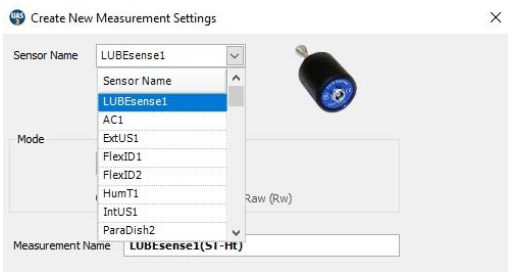
Assigning LUBExpert Sensors
If you followed the instructions to go into LUBExpert Mode, the list of available sensors should only be two (LUBEsense and TEMP2). The other sensors are still visible but inactive. Choose LUBEsense to create an ultrasound measurement node and TEMP2 to create a temperature measurement node as required.
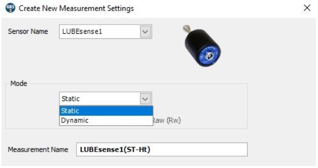
For ultrasound measurements, UAS2 gives you the option to choose either Static or Dynamic and for temperature measurements you can set the measurement interval and the emissivity. The LUBExpert instrument in standard version does not measure Dynamic data, but LUBExpert Dynamic does. In case you operate with LUBExpert standard, choose Static measurement settings, otherwise your instrument will not recognize Dynamic settings. LUBExpert Dynamic will accept Dynamic measurement settings and collect Dynamic data during grease replenishment process.
Same happens if you are using an SDT270DU with the LUBExpert App installed, choosing Dynamic here will instruct your SDT270DU to collect both Dynamic and Static data simultaneously.
Setting the interval of data collection
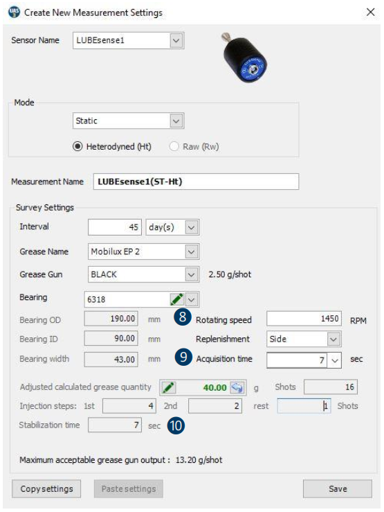
For both LUBEsense and TEMP2 measurements, the choice to set your preferred data collection interval time ❶ in months, weeks, days, or hours ❷ is made here.
Note that this field is not intended to be the re-greasing interval. This field is your data collection interval.
Condition assessment based on measured ultrasound data will be the trigger to perform grease replenishment (or not) as well as the quantity of grease required to restore an optimal lubrication mechanism to the bearing.
For TEMP2 measurements the additional choice to set emissivity exists here. The default emissivity is 1.0.
Setting Grease Type
Earlier we described how to set up a list of all the lubricant types used in your plant under “Lubricant Management”. With the “Create New Measurement” dialogue box open, here you select the grease type for this bearing using the drop-down box beside the field Grease Name ❸.
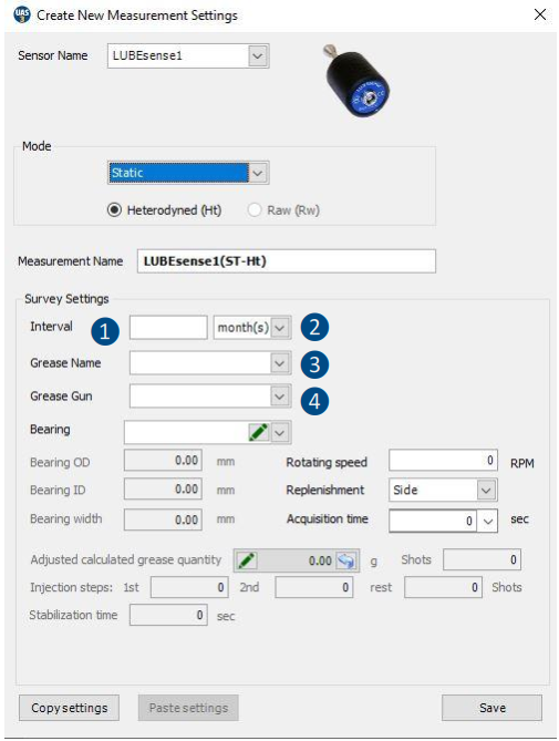
Setting Grease Gun
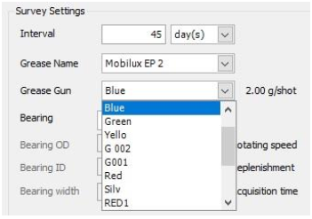
Earlier we described how to manage your inventory of grease guns under “Grease Gun Management”. In that section, you named your grease gun and entered its grease injection quantity per stroke. Now, as you create measurement collection points in UAS3, it is important to assign the correct grease gun to the correct asset. Click on the drop-down box and scroll to the grease gun name to be used. Hover and release your mouse to select ❹.

Assigning bearing data to Lube point
UAS3 manages a bearing database. This puts bearing dimensions conveniently at your fingertips. In the field Bearing ❺, you must assign bearing data to the lube point, so all the necessary and automatic settings are then filled by UAS3. In field ❺, choose the drop-down menu where you will see all the bearing types currently available within the UAS3 bearing database. Alternatively, you can click “EDIT” and add new bearing types.
Assigning bearing types already in the database
Select the drop-down menu in field ❺, browse the database and select the desired bearing.
Adding new or editing existing bearings to the database
Select “EDIT” in field ❺ and create new bearing, edit or delete existing bearing types. In case you do not know the type of the bearing installed, create a new one with a temporary name and approximate size and input accurate data at the first possible opportunity.

Manual input of grease quantity
If you want to manually add calculated grease quantity, chose “Edit” in field ❼ and enter the quantity. In this case, all pre-calculations will be done based on your input. Manually edited quantity will be shown in Italic. If you want to go back to automatically calculated qty, simply press the “go back” arrow in field ❼. Note that the bearing must be selected, at least temporary one, with an approximate size. Editing quantity by more than 30% might cause guidance malfunction.
Side or Annular replenishment
In field ❻, you need to choose if grease replenishment is side or annular. Select “side” or “annular” from the drop-down menu. Note! If you chose to edit calculated grease quantity manually, this field will be blocked. ❺

Once you have selected a bearing that is actually installed in the asset as well as its replenishment position, OD, ID and Width are defined, and grease quantity is calculated and adjusted according to selected grease pump output. This quantity is used as a safety point only in case of “Suspected Bearing Failure” status and to provide automatic recommendation to “Shorten Interval” that you have selected. Based on asset data selected at this point, UAS3 is also able to calculate steps in your guided lubrication process. In this example, step one will be 5 shots injection, step two 3 shots, step 3 and all following steps 2 shots.
Setting rotational speed
In order to complete the setup, UAS3 also needs information about the rotating speed of the selected asset. Enter the rotational speed in RPM in field ❽. In case you are not sure about the rotating speed, or it is variable, set the lowest expected rotating speed to be on the safe side.

Acquisition time
Based on rotating speed, UAS3 will automatically calculate minimum and recommended acquisition time ❾
Recommended time is the result of positive experiences, but if desired, you can choose minimum time or any other acquisition time, but not less than minimum time and not greater than 80 seconds.
Stabilization time
Based on previously inserted data, UAS3 now automatically calculates the stabilization time and displays it in field ❿
Press “SAVE” and all settings for the selected asset are ready. These settings are assigned to the selected asset and go with it when workorders are transferred to the LUBExpert instrument. No further settings need to be done (nor can be done) in LUBExpert once in the field. This enables your grease technician to have comfortable, fast, and safe work in the field, as well as tight work control and dependable data for the Lubrication Manager.
10.4. Adding an Event
Event is additional textual information assigned to asset. It contains certain message (what) and date (when). Events can be added in UAS3 and in instrument itself (as automatic or manually added messages). Adding events has a great value for better understanding of data and for easier use of database. They represent certain observations or comment, some action that is important to be ❽ ❾ ❿ logged, represent Lubrication decision flow, but are also highly valuable as flags in time making your searches or analytics easier.
Event can be assigned to Asset, Measurement Point (SDT340), and Tree Node (SDT270 & LUBExpert). Even can not be added at sensor level.
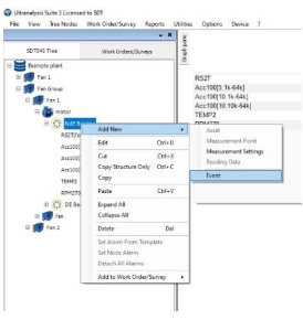
Right click on Tree Node, choose Add New and click on Event.
Event window will pop up:
Enter Description of Event and click on Save. Even is added and it will be displayed in Static Trend and Bottom Pane, and it can be use in data filtering.
Manually added events in UAS3, or manually added messages in instrument (both treated as events) are marked with (M).
Automatically added messages in instrument (LUBExpert) are equally treated as events and marked with (A).
10.5. Copying and Pasting Nodes
Once engaged in building a database, you will often face similar equipment, similar configurations, sometimes practically identical groups, or processes. Obviously, there will be lots of copy/paste at certain point. You can cut, copy and paste Measurement Settings (Sensor level), Asset Component, Asset or entire group (branch). Look at situation below:
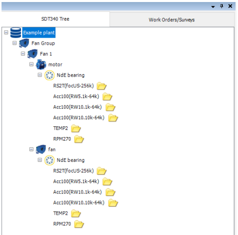
In our Database Root, Example Plant, we created a Fan Group. Within Fan Group we have Fan 1 containing motor and fan. Both motor and fan contain one Measurement Point each, with detailed Measurement Settings. But, in reality, we have several fans in this Fan Group, both motor and fan have two bearings, of course, and throughout the plant, we have several Fan Groups like this one.

Let us start with completing motor and fan. Right click on NdE bearing (or use Top toolbar commands), move one level up (parent node, motor) and paste it. Note that there are two tools:
Copy Structure Only – Structure will be copied with all settings, but measurement data will not be copied, very useful when building Tree Structure or expanding it.
Copy – Entire point will be copied, including measurement data. Very useful when component or Asset are moved to a different location, or when partial backup needs to be done.
Select one level up (parent node, motor) and click on Paste.
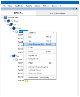
NdE bearing is now pasted in Node motor, with name NdE bearing (1).

Now right click on newly pasted NdE bearing (1) and select Edit and rename it to DE bearing.

Now we have completed motor and fan, but we might want to copy/paste entire Fan 1, as we have more than one Fan in Fan Group. Process is same. Right click on Fan 1, select Copy Structure Only (if we don’t want to copy measurement data as well), right click on Fan Group (parent node) and select Paste. Edit the name (example Fan 2).
Note
Sensor Level (Measurement) cannot be pasted into the Node that already contains same Measurement Name or Category Name. Sensor Level (Measurement) cannot be pasted into the Node that contains other nodes, it can only be pasted into Measurement Point level. If you need to copy/paste certain nodes into another Tree Structure, process is same as shown here for copy/paste within same Tree Structure. Copy Node you need, open another Tree Structure and Paste it.
10.6. Drag and Drop Data
Measurement Settings (Sensor Level) can be copied from Bottom Pane into the Tree Structure. To select the data you want to move, press, and hold on the left button of your mouse.
Use Shift and Ctrl to select multiple data.
Drag the data to the desired Location on the Top Pane.
Hoover your mouse over desired location in the Tree Structure, and it will open child nodes down to the measurement level where you can paste. Drop the data by releasing the left button of the mouse. Equally, you can drag and drop data within the Tree Structure.
10.7. Insert a Static Data
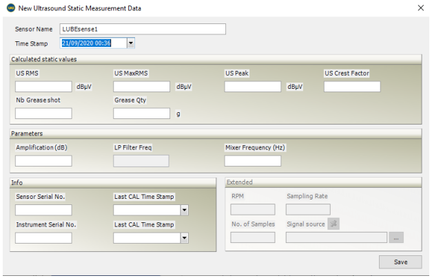
UAS3 allows you to insert static data manually. Right click on a Static Measurement. On the dropdown menu, select Add New/Reading Data.
The following window is displayed:

The field Sensor Name is filled automatically by UAS3.
Choose the date of the Data by clicking the drop-down menu Time Stamp.
Please fill the field RMS (for US sensors and accelerometers), or Value (for the other sensors) with a numerical value. This field is mandatory while the following are optional.
Click Save to finish the operation.
10.8. Import Dynamic Data or Wave file
You can import a wave file into UAS3, and you will be able to analyze the time signal and eventually the spectrum. However, it is possible that values (amplitudes) will not be accurate since not all data (amplification for instance) will not be available.
To import Dynamic Data, right click on a Dynamic Measurement.
On the drop-down menu, select Add New/Reading Data.
The following window is displayed:
Click the browse button '...' (elipses), placed under the field Signal Source and then select the name of the wave file and its location.
Click Save to finish the operation.
10.9. Working with Work Orders/ Surveys
Work Order/Survey is an organized task extracted from Tree Structure. It contains selected Assets and Measurement Points in pre-defined order, all Measurement Settings and Alarms, allowing field operator to execute data collection in clear, fast and an efficient manner. Clear, fast, and efficient also results in Safe, by minimizing field work. Executing task through Work Order/Survey assures that data is collected using same settings, thus being comparable for further analysis.
Work Order/Survey is created by selecting and adding items from your Tree Structure.
- One item can be in several Work Order/Survey.
- Work Order/Survey does not affect Tree Structure.
- You can create as many Work Order/Survey as you need, no limitations.
- Work Order/Survey can contain items from one Tree Structure only.
Work Order/Survey must be designed with practicality of field work in mind.
Way the Assets are organized in Tree Structure should reflect needs of person using UAS3, to be able to overview Data in most efficient and logical manner.
Way the Measurement Points are organized in Work Order/Survey must reflect needs of person using instrument in the field, they should be set in logical order that reflect reality of work.
Those two aspects do not necessarily align. Needs might be different. For that reason, you are able to organize your Work Orders/Surveys in different way and independently of the Tree Structure sequence.
In practice, you need to consider several aspects:
- What Assets are located in the same area?
- What Assets operate at the same time?
- What is the best sequence of data collection, regarding ability to approach Asset?
- What are the competences and clearances of field technician (electrician? mechanic? process?)
- What Assets require data collection at the same or similar interval?
- How much time will it take to execute a Work Order/Survey (do not make it a big, boring job, multiple smaller tasks are more likely to get done properly)
Best practice is to consult field team and understand what the safest, most comfortable, and most efficient way is to collect data in the field. As person generating Work Orders/Surveys, you should create one, walk it yourself, consult others, adjust it, and only then consider it final.
Items can be added to Work Order/Survey in several ways.
- Add items from the Tree Structure (using mouse right click or Top toolbar commands)
- You can add single measurement
- You can add any tree node and it will contain all child nodes
- Add items from the Bottom Pane
- Select items and add them
- Filter items based on certain criteria and add them
- Add items from To-Do List
- Search items by their data collection due date and add them
Here is how to do it:
10.9.1. Add entire Tree Structure to Work Order/Survey
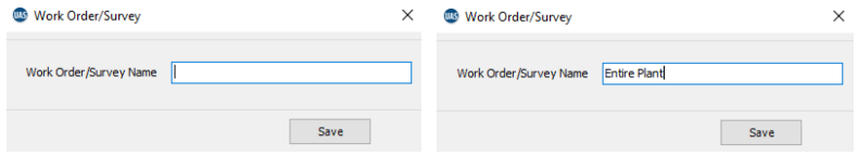
Right click on 1st level of Tree Structure, Database root and select Add to Work Order/Survey, choose instrument you work with, and choose if you want to add items to New Work Order/Survey or to Add to Existing.
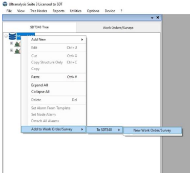
Work Order/Survey window will pop up where you need to assign Work Order/Survey Name.
Use name that is intuitive and can be easily understood by everyone.
Once name is assigned, press Save.
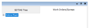
Your Work Order/Survey is generated. It is placed in Top Pane, in Work Orders/Surveys tab.
10.9.2. Add certain Nodes from Tree Structure to Work Order/Survey
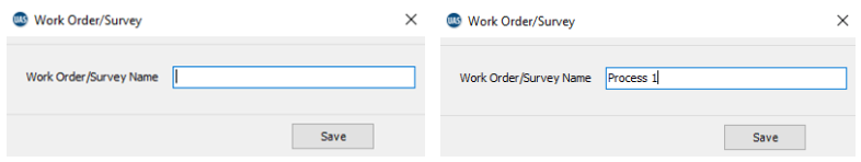
Right click on the Node you want to add and select Add to Work Order/Survey, choose instrument you work with, and choose if you want to add Node to New Work Order/Survey or to Add to Existing.

Work Order/Survey window will pop up where you need to assign Work Order/Survey Name.
Use name that is intuitive and can be easily understood by everyone.
Once name is assigned, press Save.
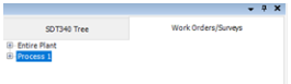
This new Work Order/Survey is added to list of Work Orders/Surveys:
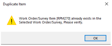
You can do the same with any portion or single item from your Tree Structure. However, if you try to add and item to existing Work Order/Survey, and that item already exists there, UAS3 will warn you that item will be duplicated and ask for confirmation.
10.9.3. Add items from Bottom Pane to Work Order/Survey
Bottom Pane displays all measurements contained in Tree node you selected:
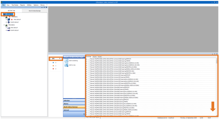
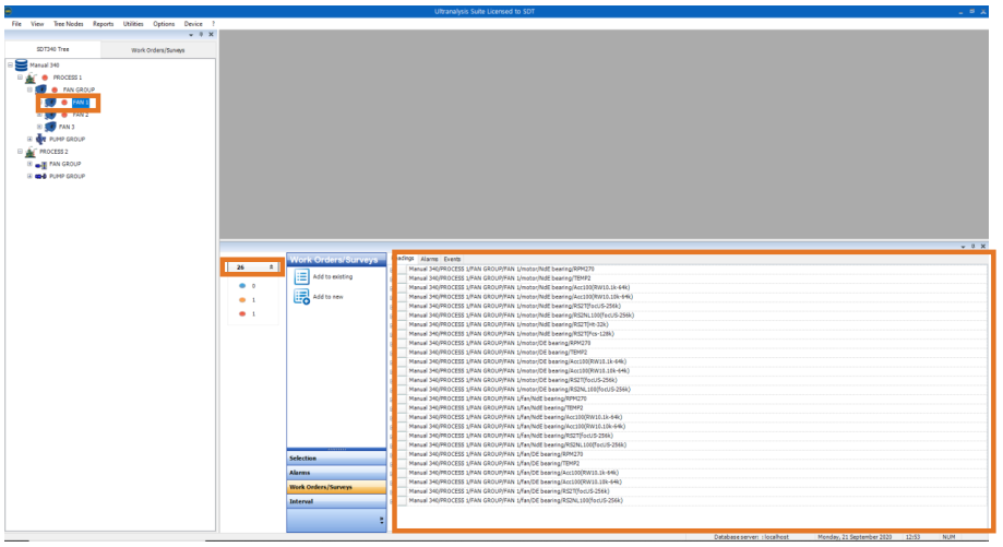
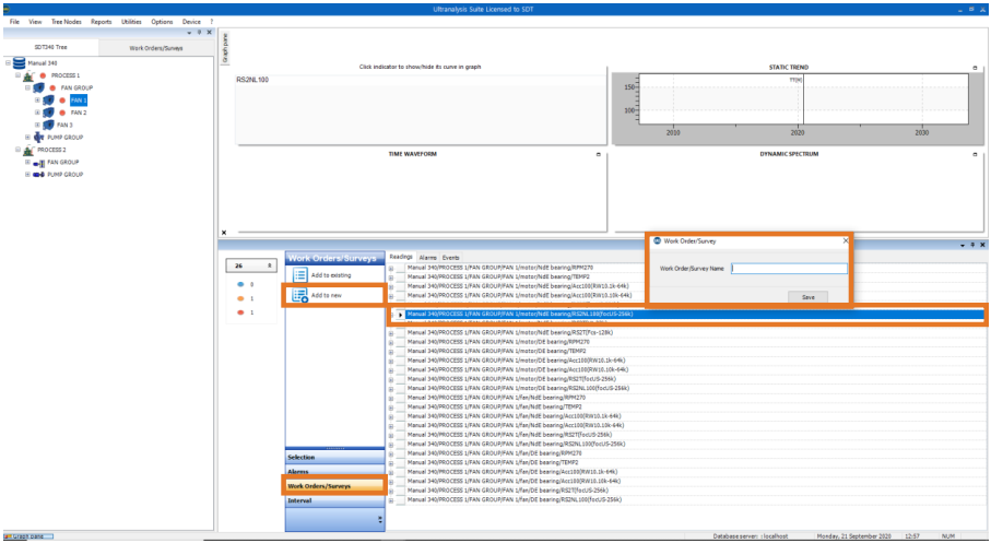
From Bottom Pane you can select any measurement (left click on the measurement), selecting Work Orders/Surveys in the Toolbox and add it to new Work Order/Survey or to existing one, as below:
Instead of selecting items individually, you can Filter them by certain criteria and add them as a group. Select Selection in the Toolbox, select Filter, and small Filter window will appear at the bottom of Bottom Pane, as below:
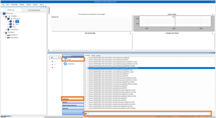
Use Filter window to enter criteria. As you enter one criterion, list will be narrowed to all items containing criteria (word) you entered. Use “;” to add more criteria and narrow your search further.
Once you are done with filtering, you can select from the list in Bottom Pane, and add it to Work Order/Survey. To select multiple items, use “shift” or “ctrl”.
10.9.4. Add items from To Do List to Work Order/Survey
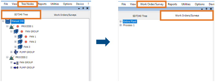
To Do List contains items based on data collection due date (based on interval you defined in settings). Due date consideration for each item starts with first data collection. In Top Pane, select Work Orders/Surveys tab and Work Order/Survey button will appear in Top toolbar instead of Tree Nodes.
Left click on Work Order/Survey in Top toolbar and left click on To Do. To Do window will appear, where you can select period or two additional criteria; Missed measurements and Never measured points.
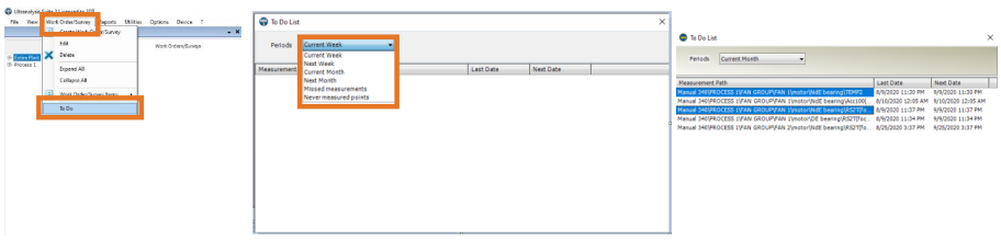
Once criteria are selected, all items that meat criteria will appear. Due date is quite clear criteria, and it filters data collection scheduled in period you choose, according to their set interval (consider that interval starts the count once first ever measurement has been taken). Missed measurement is very useful criteria, as it will filter out all data collection tasks with past due date (as those do not fall into previously mentioned criteria). Never measured points criteria filters out all measurement points with no data (newly introduced to database, newly installed assets …) reminding you that it needs to be done. From this window, you can select filtered points (single or multiple select) and with right click add them to new or existing Work Order/Survey.
10.9.5. Change Measurement order in Work Order/Survey
You can re-order the sequence of data collection and grouping Measurements into an order which is more efficient from a data collection point of view simply by selecting a
Measurement and while holding the left mouse button, dragging it to a new position and then release the left mouse button.
This does not affect the Tree Structure in any way and how the data is stored in the database, it just makes it easier for you to collect it.